How to choose professional optical module manufacturers?

Due to optical modules on the market are endless and dazzling, many people do not know how to choose a suitable optical module manufacturer when purchasing optical modules.Next, Sanland will teach you how to find a third-party compatible module supplier with high cost performance?


Quality management system and certification qualification.

Manufacturers need to have ISO9001 quality management system and CE, ROHS, FCC certification.


Complete test equipment.

Manufacturers need to have a full set of test equipment, common equipment are optical attenuator, optical power meter, error code meter, eye chart instrument, brand switch, etc.


Systematic testing process

Good quality optical modules will go through product appearance test, parameter test, compatibility and connectivity test and optical end surface cleaning before shipment. However, not all optical module suppliers have complete test equipment, so it is better to choose the optical module suppliers who can provide factory test reports or the optical module has passed the switching test / simulated scene test, such as Sanland.


Module warranty time

The normal service life of an optical module is 5-6 years. The optical module provided by sanland has a two-year warranty and lifelong technical support.


Perfect storage system

The suppliers of compatible optical modules with a large amount of stock and perfect warehouse system represent that they have the ability to respond quickly, deliver goods in time, and respond to the needs of customers in different regions.


Service capability

The service of compatible optical module manufacturers is mainly reflected in product service, technical support, inventory support, pre-sale and after-sale service, etc.


Technical support

For some small enterprises, campuses and units, due to the lack of network administrator technology, network planning and design and network deployment technology problems can not be solved. If a compatible optical module supplier has a professional technical team, it can provide technical support, provide customized network deployment solutions for customers, and effectively and quickly solve the technical problems of network deployment.


In short, the cost performance of optical module should be considered when selecting optical module supplier, not just the price of optical module alone. Facing many optical module suppliers, we must not only see the price gap of tens of yuan, but also consider a series of strength of product quality, technical strength and service of the optical module supplier.

Whether it is an enterprise network or a home network, fast and reliable Ethernet is an inevitable requirement. With the maturity and popularization of 10G Ethernet technology in the commercial field, the cost of 10G network deployment has been greatly reduced. Because of this, some home users have begun to consider upgrading the previous 1G optical fiber home network to 10G, but for home users , 10G optical fiber network is a new field.


What equipment is needed when deploying 10G home optical fiber network?


For 10G home optical fiber networking, home 10G switches, routers and wireless access points (APs) are essential components. Depending on the requirements, devices such as network servers, 10G network cards, PoE switches, and IP cameras may also be required in the home network.


How to choose the best equipment for 10G home fiber optic network?


Home Network Switch

For 10G home fiber optic network, you may need 10 Gigabit network switch and PoE switch


1. Function and performance

Network switches have many functions, especially managed network switches. However, for home network switches, it is not necessary to choose a network switch that supports all functions, but choose to support basic functions, such as QoS, VLAN, and security. At the same time, you can also consider the stacking function and power over Ethernet function. The stacking function can bring higher flexibility to the network. If you want to upgrade the network later or need to add more network devices to the network, stacking multiple switches may be the most effective and economical solution, because it can be used in Meet your needs without changing the original network architecture. The Power over Ethernet function can supply power to PoE devices. If you need to deploy PoE devices such as IP cameras in your home network, it is recommended that you choose a switch that supports Power over Ethernet (PoE switch or PoE+ switch).

In addition, power consumption and capacity are also factors to be considered. Since the larger the switching capacity, the stronger the data exchange capability of the switch, in order to ensure the stable and reliable operation of your home network, it is recommended to choose a network switch with a larger switching capacity. At the same time, it is necessary to choose a fanless network switch for home networking, because the fanless network switch is basically noiseless and helps to reduce system power consumption.


2. Port

Generally, the port types of home network switches include electrical ports (that is, RJ45 ports) and optical ports (such as SFP/SFP+ ports). Among them, electrical ports are generally connected with Cat6 network jumpers, while optical ports generally need to be used with optical modules and fiber jumpers, such as SFP+ ports are generally used with SFP+ optical modules and LC duplex fiber jumpers. . In addition to considering the port type, the number of ports on the home network switch is also a factor that needs to be considered. If your network does not need to connect many network devices, generally speaking, an 8-port or 12-port 10G switch can meet the demand; but If you need to connect a lot of network devices or the network scale will expand in the short term, it is recommended that you choose a 24-port or 48-port 10G switch. All in all, all choices are based on your actual network needs.


3. Cost

Because the cost of the electrical port is lower than that of the optical port, the cost of the electrical port (ie RJ45 port) network switch is generally lower than that of the optical port network switch. Managed network switches are also more expensive than unmanaged network switches. After determining the type of home network switch, you can compare the home network switches provided by different suppliers on the market and choose the most cost-effective one.


Home Router

A router is an essential device that connects your home network to the Internet. Compared with home network switches, the choice of home routers is much simpler. First of all, you should contact your Internet Service Provider (ISP) or check your account details directly to obtain your bandwidth rate and see how high a rate router is needed to handle the bandwidth rate. Considering that you are now cabling your 10G home fiber optic network, the router you choose should have at least one SFP+ port. Secondly, you need to determine the type of router you need. Currently, routers are divided into wired routers and wireless routers. Although wireless routers can provide both wireless or Ethernet connections, their wireless WiFi signal coverage is limited, and they are usually more expensive than wired routers. Therefore, if your home network covers a large area, considering the cost and the stability of the connection, it is recommended that you give priority to a wired router (which can be used with a wireless access point).


Home Wireless Access Point

A wireless access point is essential if you want your wireless devices to be able to access the Internet. When choosing a wireless access point, you must first confirm several questions: How many wireless devices do you have? What is the maximum area that a WiFi signal needs to cover? How far can your chosen wireless access point cover? After confirming these questions, you can determine how many wireless access points need to be purchased, so that you can avoid choosing too few or too many wireless access points.


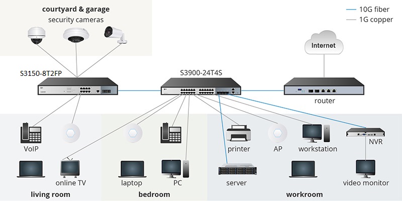
After selecting the network equipment, it is time to deploy the 10G home optical fiber network. A typical 10G home optical fiber network deployment diagram is as follows. There are many network devices in the whole house. After calculating the connection lines, the 24-port 10G switch is used as the core switch in the home network. Among them, the 24 ports of the 10G switch The ports are connected to most terminal devices, and the 4 SFP+ optical ports of the 10G switch are connected to PoE+ switches, routers, network video recorders (NVR) and servers. As for PoE devices in yards, garages, etc., just connect them to an 8-port PoE+ switch.


Optical module structure and main use


Due to the technical development trend of electronic information technology, digital power amplifiers and passive optical components, the integrated optical transceiver module has become the main product of general optical modules in recent years. Although the packaging, speed and transmission distance of optical modules are different, their internal structure is basically the same. Now let's master and explore the principle of optical modules.


The main Use of optical module

Optical module is used medium for transmission between network switches and machinery and equipment, And is the main commodity in the optical communication system.The design principle of the optical module is to achieve the optical and electro-optical transformation photoelectric material commodity. The upload end of the optical module converts the electronic signal into an optical signal, And the coordinator converts the optical signal into an electronic signal.


Optical Module Stucture

The optical module is composed of multiple parts such as optoelectronic devices, power supply circuits and optical sockets.Optoelectronic device consists of two parts: send and transmission.


Optical module classification

Optical modules can be divided into optical receiver modules, optical push modules, Optical transceiver modules and share modules etc.The optical transceiver module key function is to complete the optical/electrical-optical conversion,Including laser power control, blend push, Data signal detection and its clipping and magnification, adjudication and reconstruction,Common are:SFP、SFP 、XFP 、SFP28、QSFP 、QSFP28 etc.

As the demand for high-quality video and internet services continues to grow, CATV networks are increasingly relying on advanced optical receiver modules to provide superior performance. These optical receiver modules are integral to ensuring that cable television (CATV) systems, fiber-to-the-home (FTTH) solutions, and high-speed internet services operate with minimal interruptions and high signal quality. A well-designed optical receiver module can significantly reduce noise and enhance the overall network experience.


One of the key features of a cutting-edge CATV optical receiver module is the Custom AGC (Automatic Gain Control). AGC technology ensures that the receiver maintains consistent output levels despite fluctuations in the input signal. This is particularly beneficial in CATV systems, where signal strength may vary due to distance or environmental factors. With a custom AGC optical receiver module, network operators can optimize signal quality, reduce distortion, and improve the overall reliability of the service.


Additionally, low noise is a critical factor in ensuring the quality of the received signal. Low Noise Optical Receivers are designed to minimize the interference that can degrade the signal, ensuring that high-definition video and other services are delivered without degradation. These low-noise modules are essential for CATV operators seeking to provide high-quality content without interruptions or quality loss, even in densely populated urban environments or challenging network conditions.


The increasing adoption of FTTH solutions has also raised the need for specialized optical modules that can cater to high-speed data demands. With the rapid expansion of fiber optic networks, operators need equipment that can handle large amounts of data without sacrificing speed or reliability. The use of advanced optical receiver modules in FTTH solutions ensures that high-bandwidth services like IPTV, VoIP, and internet access are delivered seamlessly to consumers, driving higher customer satisfaction and reducing churn.


At Sanland, we understand the evolving needs of the telecommunications industry. Our CATV Optical Receiver Modules for G-PON and XGS-PON applications offer customizable features tailored to the unique requirements of each network. Whether it’s optimizing for low noise, custom AGC, or high-speed FTTH solutions, our products are designed to deliver exceptional performance.   optical receiver module


Sanland stands out not only because of the superior quality of our products but also because of the value we bring to our clients. Our ability to provide customized solutions means that we can work closely with you to meet your specific network requirements, ensuring that you always have the best equipment for your needs. From the design phase to after-sales support, our team is committed to delivering top-tier service and ensuring that your network is performing at its best, all the time.


For businesses looking to upgrade their CATV or FTTH systems, choosing Sanland’s optical receiver modules means choosing quality, reliability, and exceptional service. Sanland is dedicated to helping you build robust, efficient, and high-performance networks that keep your customers connected and satisfied.

The difference between Passive Optical Network (PON) and Active Optical Network (AON)


Passive optical network (PON) and active optical network (AON) are two access technologies for building DWDM and CWDM backbone networks in FTTH systems. Both have their own advantages, so what are the main differences between them? How should we choose?


Signal Distribution

The difference in signal distribution is the biggest difference between passive optical network (PON) and active optical network (AON). In a passive optical network (PON), there is a situation where optical fiber bundles are shared between users, while in an active optical network (AON), each user has an independent optical fiber chain, and there is no shared bandwidth between each other , Therefore, relatively speaking, the passive optical network (PON) system does not run as fast as the active optical network (AON), and it is more difficult to troubleshoot when a fault occurs.


Cost

As we all know, the main sources of network costs are power supply equipment and maintenance costs. It can be seen from the above that the passive optical network (PON) has no other power supply equipment except for both ends, and requires less maintenance and no power supply; while the active optical network (AON) mainly uses power supply equipment for network transmission, so relatively In general, the cost of active optical network (AON) is higher than that of passive optical network.


Coverage

Passive optical networks (PONs) typically only cover distances up to 20 kilometers, while active optical networks (AONs) can cover distances up to about 100 kilometers. In other words, users in the passive optical network (PON) must be closer to the input signal.


Application Range

In addition to the factors mentioned above, practical applications also need to consider other factors. For example, when it comes to radio frequency deployment and video services, it is more appropriate to choose Passive Optical Network (PON); if the target users have higher requirements on the network or a large number of users (such as commercial customers or multiple residential buildings), choose Active Optical Network (AON) is more suitable.


In addition to the differences mentioned above, there are other differences between the two networks. For example, industry standards, popularity, etc.

What are the parameters of the optical module?


The parameters of optical module mainly include transmission rate, Center wavelength, Transmission distance, Single-mode/multi-mode, Interface type, etc.


Multimode has large loss but small dispersion during transmission, And is suitable for short-distance transmission, While single-mode has small loss but large dispersion during transmission, And is suitable for long-distance transmission.


Loss refers to the loss of optical energy caused by absorption, scattering and leakage of the medium when light is transmitted in the optical fiber. This part of the energy is dissipated at a certain rate with the increase of the transmission distance.


Dispersion occurs mainly because electromagnetic waves of different wavelengths travel at different speeds in the same medium. As a result, Different wavelength components of the optical signal reach  the receiving at different times due to the accumulation of transmission distances, Resulting in pulse broadening and inability to distinguish signal values.


Above all is the entire content of optical module parameters. For more information on optical module products, please follow the official website of Sanland Technology. Thank you for your support!

At present, an effective method to solve the increasing bandwidth of information transmission is to use CWDM equipment and DWDM equipment, but they are different in many aspects.


1. Channel spacing between CWDM equipment and DWDM equipment


Channel spacing is defined as the difference between the nominal carrier frequencies of two adjacent optical channels, and is generally used to prevent inter-channel interference. CWDM  has a wider spacing than DWDM, it can transmit 18 wavelengths in the spectral grid of 1271 nm to 1611 nm, and the channel spacing is 20 nm. DWDM can transmit 40, 80 or 160 wavelengths, and the channel spacing can be 0.8 nm.


2. Transmission distance between CWDM equipment and DWDM equipment

Since the wavelength of dense wavelength division multiplexing equipment (DWDM) is highly integrated during optical fiber transmission, DWDM equipment can transmit longer distances than CWDM equipment. CWDM equipment currently cannot achieve unlimited distance transmission, and its maximum transmission distance is only 160 kilometers, while the transmission distance of DWDM equipment far exceeds that of CWDM equipment.


3. Modulated lasers of CWDM equipment and DWDM equipment

The system of CWDM equipment has lower requirements on the technical indicators of the laser, and generally an uncooled laser can be used; the system of DWDM equipment needs to use a cooled laser, and the cooling laser adopts a temperature adjustment method to ensure the stability of the DWDM system. With better performance, higher safety and longer service life, DWDM consume more energy than CWDM equipment.


4. Cost of CWDM equipment and DWDM equipment

Because the temperature distribution of the DWDM equipment system is uneven in a wide wavelength range, when the cooling laser technology is used to adjust the temperature, the use cost of the DWDM equipment system is increased. In addition, the system of DWDM equipment is usually four to five times more expensive than the system of CWDM equipment. However, with the increasing popularity of DWDM, the price of DWDM optical modules is nearly 20%-25% lower than that of CWDM optical modules.

What is the Recrystallization Process?


Recrystallization is an important phenomenon in materials science that involves the microstructural recovery of material after plastic deformation. This process is crucial for understanding material properties and optimizing processing techniques.


Mechanisms and Classification of Recrystallization


Recrystallization processes are typically triggered by heat treatment or thermal deformation and involve the natural recovery of materials after the generation of defects during deformation. Defects such as dislocations and grain boundaries promote the reduction of system-free energy at high temperatures through dislocation rearrangement and annihilation, leading to the formation of new grain structures.

Recrystallization can be classified into static recrystallization (SRX) and dynamic recrystallization (DRX). SRX occurs during annealing processes, while DRX takes place during thermal deformation. Furthermore, recrystallization can be further subdivided based on specific mechanisms, such as continuous dynamic recrystallization (CDRX), discontinuous dynamic recrystallization (DDRX), geometric dynamic recrystallization (GDRX), and metadynamic recrystallization (MDRX). These classifications are not strictly defined, and researchers may have different interpretations.


Factors influencing recrystallization


The recrystallization process is influenced by various factors, including the stacking fault energy (γSFE), initial grain size, thermal processing conditions, and second-phase particles. The magnitude of the stacking fault energy determines the dislocation breakdown and mobility, thereby affecting the recrystallization rate. Smaller initial grain sizes and suitable thermal processing conditions, such as high temperature and low strain rates, facilitate recrystallization. Second-phase particles can significantly influence the recrystallization process by hindering grain boundary motion.


Application of imaging techniques


EBSD and TEM are two classic imaging techniques used in recrystallization studies. EBSD analyzes the distribution and percentage of recrystallized grains using the DefRex map, although resolution limitations may pose accuracy issues. TEM, on the other hand, provides a direct observation of material substructures, such as dislocations, offering a more intuitive perspective for recrystallization studies.


Application of EBSD in recrystallization studies


EBSD is used to determine whether grains have undergone recrystallization by observing grain boundaries. For example, in the DefRex maps of forged TNM alloys, grains surrounded by high-angle boundaries are typically considered recrystallized grains. This technique provides detailed information about grain orientations and grain boundary types, aiding in the understanding of microstructural changes during recrystallization.


BC+GB (grain boundary) map of forged TiAl alloy


Application of TEM in recrystallization studies


TEM allows for more in-depth observations. For instance, in TEM images of rolled TiAl alloys, defect-free equiaxed grains, which are recrystallized grains, are clearly visible. This technique reveals the submicron-scale structures of materials, including dislocation arrangements and grain boundary characteristics, which are essential for understanding recrystallization mechanisms and optimizing material properties

In modern society, more and more attention is paid to saving energy and reducing carbon emissions. With the increasing demand for energy conservation and emission reduction in the global market, the market demand for high light efficiency chips is also growing.


What are high light efficiency chips?

High-efficiency chips ‌are those that produce more light output for the same amount of power and are commonly used in lighting and display devices. This kind of chip has the advantages of high luminous efficiency, energy saving, environmental protection, long life, etc., and is a high-performance component commonly used in modern electronic equipment.


What are the technical characteristics of high light efficiency chips?

1. High Luminous Efficiency: Can efficiently convert electric energy into light energy, reduce energy consumption.

2. Energy Saving and Environmental Protection: The use of high light efficiency chips can significantly reduce energy consumption and reduce carbon emissions.

3. Long Life: Compared with traditional light sources, high light efficiency chips have a longer life, reducing replacement frequency and maintenance costs.

4. Small size: High light efficiency LED lights are small in size and suitable for installation needs of various application scenarios.


High Light Efficiency LED Farming Light

In terms of lighting, high light efficiency LED lamps have better energy-saving effects and longer service life than traditional incandescent lamps and energy-saving lamps. For example, after the use of high light efficiency chips, our LED Poultry Farming Light products have been upgraded to High Light Efficiency LED Poultry Farming Light products. It can efficiently convert electric energy into light energy, reduce the loss of electric energy into heat energy, improve the overall energy efficiency, and thus reduce energy consumption. The bulbs have a long service life, can work tens of thousands of hours continuously, reduce the cost of replacement and maintenance. This is an outstanding example of Environmental Friendly LED Poultry Farming Light.


As cities around the world become more connected and technologically advanced, interactive flat panels (IFPs) are emerging as key players in shaping the future of smart cities. These cutting-edge displays go beyond traditional screens, offering interactivity, real-time information sharing, and collaboration. As urban spaces continue to evolve, IFPs are playing an increasingly vital role in creating more efficient, sustainable, and inclusive communities.


Here are five compelling reasons why interactive flat panels are set to revolutionize smart cities:


1. Revolutionizing Public Spaces with Digital Signage and Information Dissemination

In a smart city, public spaces are not just areas to pass through—they are hubs for communication and engagement. IFPs are transforming public spaces by providing dynamic digital signage that goes far beyond static advertisements. From interactive kiosks in malls to real-time bus schedules at transportation hubs, IFPs serve as the heart of a city’s digital communication system.

  • Real-Time Information
  • Interactive Engagement
  • Localized Content


2. Smart Classrooms and Public Libraries: Bringing Education into the Digital Age

As education becomes more technology-driven, smart classrooms and public libraries are increasingly turning to interactive flat panels to enhance learning and collaboration. These digital tools provide more than just a display—they create an interactive learning environment that adapts to the needs of students and educators alike.

  • Interactive Learning
  • Enhanced Accessibility
  • Collaboration and Inclusion


3. Enhancing Smart Transportation Systems with Real-Time Information

Transportation is a critical component of any smart city, and IFPs are playing a significant role in improving the way people navigate and experience urban transit systems. From bus stations to subway entrances, interactive flat panels are transforming transportation hubs into smarter, more efficient spaces.

  • Real-Time Transit Updates
  • Interactive Maps and Navigation
  • Smart Ticketing


4. Promoting Public Engagement and Community Innovation

Public engagement is a key principle in building a successful smart city, and interactive flat panels are an effective tool for fostering communication between city authorities and citizens. IFPs can serve as a platform for public participation in decision-making processes, community-driven innovation, and civic engagement.

  • Participatory Decision-Making
  • Community Projects and Initiatives
  • Collaborative Innovation


5. Integrating Interactive Flat Panels into Smart City Infrastructure

As smart cities continue to evolve, the integration of interactive flat panels into the broader city infrastructure is key to unlocking their full potential. IFPs can serve as a foundational element in connecting and streamlining urban systems.

  • Centralized Control and Management
  • Sustainability
  • Seamless Integration with IoT


The integration of interactive flat panels into smart city frameworks is ushering in a new era of urban living, where communication is more dynamic, transportation is more efficient, and public engagement is more inclusive. By enabling real-time information sharing, collaboration, and interactivity, IFPs are playing a central role in transforming cities into smart, sustainable, and connected communities. As technology continues to evolve, interactive flat panels will undoubtedly be a driving force in shaping the cities of tomorrow.